
Selection Guides
4–20 mA vs 0–10 V vs RS485: Choosing a Transmitter Output Signal
How transmitter output signals differ where it counts — distance and noise, wire-break diagnostics, power supply, multi-point wiring and PLC compatibility — and which signal to specify for temperature and pressure transmitters in machines, plants and monitoring networks.
The sensor gets the attention, but the output signal decides how the measurement survives the journey to the controller. The same temperature or pressure transmitter is often available with several outputs at near-identical prices, and the wrong pick shows up later as noise, phantom offsets, or a cabinet full of converters. Here is how the common options differ on the properties that matter.
The comparison that decides it
| Property | 4–20 mA | 0–10 V | RS485 (Modbus RTU) |
|---|---|---|---|
| Signal type | Analogue current loop | Analogue voltage | Digital bus |
| Practical distance | Hundreds of metres | A few metres to ~30 m | Up to ~1200 m per segment |
| Noise immunity | Excellent | Poor to moderate | Excellent |
| Wiring | 2 wires carry power + signal | 3 wires (power, signal, common) | Bus pair + power |
| Points per run | One per loop | One per input | Many transmitters per bus |
| Fault diagnostics | Live zero: < 3.6 mA or > 21 mA flags a fault (NAMUR NE 43 practice) | 0 V is ambiguous — real zero or broken wire? | Device-level status and error replies |
| PLC/controller inputs | Analogue input cards everywhere | Analogue input cards everywhere | Modbus port or gateway needed |
4–20 mA: the plant standard, for concrete reasons
A current loop does not care about cable resistance: the transmitter regulates the current to represent the measurement, so voltage drop along the run does not shift the reading — the failure mode that quietly degrades voltage signals. Two wires carry both the power (loop-powered) and the signal, which halves cabling against 3-wire voltage outputs. And the 4 mA "live zero" gives you diagnostics for free: a reading of 0 mA can only mean a broken loop, and transmitters following NAMUR NE 43 drive the loop below 3.6 mA or above 21 mA to actively signal sensor failure. For a single transmitter feeding a PLC across a plant, 4–20 mA remains the answer unless something below fits better.
0–10 V: right inside the machine
Voltage outputs are simple, cheap, and every small controller and OEM board accepts them. Their physics limits them to short, electrically quiet runs: the reading is the voltage at the receiving end, so cable resistance drops, ground potential differences and inverter noise all appear inside your measurement. Inside one machine or cabinet — a transmitter next to its controller — none of that matters much, and 0–10 V (or ratiometric 0.5–4.5 V in compact OEM sensors) is a perfectly rational choice. The mistake is stretching it across a plant because the transmitter happened to be on the shelf.
RS485 / Modbus: the monitoring network choice
A digital bus changes the architecture: dozens of transmitters share one shielded twisted pair, each with an address, returning engineering values (and often internal diagnostics) over distances up to about 1200 m per segment. Accuracy no longer depends on analogue conversion at the far end — the value the sensor measured is the value the controller receives. This is why cold storage, utilities, environmental monitoring and machine fleets standardize on Modbus transmitters. The costs are real but different: you need a Modbus-capable controller or a gateway, addresses and bus parameters must be managed, and update rates are polled rather than continuous — fine for monitoring and slow process loops, less so for fast closed-loop control, where a local 4–20 mA loop still wins.
HART: the hybrid worth knowing
HART keeps the 4–20 mA loop exactly as it is and superimposes a digital signal used for configuration, calibration and diagnostics. It earns its premium in large process plants with HART-capable maintenance systems; in a small installation without that infrastructure, plain 4–20 mA delivers the same measurement for less.
Choosing in practice
- One transmitter, one controller, plant distances → 4–20 mA.
- Inside a machine or cabinet, short quiet runs → 0–10 V is fine and economical.
- Many points, data collection, networking → RS485 / Modbus.
- Large process plant with digital asset management → HART over 4–20 mA.
- Mixed legacy plant → standardize new long runs on 4–20 mA; put head-mounted transmitters at sensors whose raw signals (RTD, thermocouple) would otherwise have to travel.
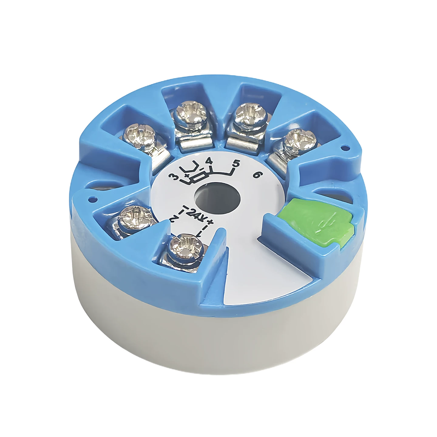
Universal Ruike temperature and pressure transmitters are offered with 4–20 mA, 0–10 V, RS485 (Modbus RTU) and HART outputs — head-mounted, rail-mounted and integrated constructions, configurable for RTD and thermocouple inputs. Tell us what the transmitter will connect to and how far away it sits, and we will match the output to the loop rather than to a catalogue default.
Related products: Temperature Transmitter Modules · Thermocouple Sensors · Industrial Pressure Transmitter